- Day 1. Inception of open-source EDA, openLANE and SkyWater 130
- Day 2. Good floorplan vs bad floorplan and introduction to library cells
- Day 3. Design library cell using Magic Layout and ngspice characterization
- Day 4. Pre-layout timing analysis and importance of good clock tree
- Day 5. Final steps for RTL2GDS using tritonRoute and openSTA
The goal of openLANE is to produce a clean GDSII layout with no human intervention. It is a fully automated open-source end-to-end ASIC design flow.
-
From
/Desktop/work/tools/openlane_working_dir/openlanewe should start docker and execute the following commands to get into the openLANE environment:
-
In this workshop we are using the picorv32a design:

-
The variables used in the configuration files (i.e.,
config.tclandsky130A_sky130_fd_sc_hd_config.tcl) are described in Day 2 and can be found in the/Desktop/work/tools/openlane_working_dir/openlane/configuration/README.md. At the beginningconfig.tclhas the following content:

-
While
sky130A_sky130_fd_sc_hd_config.tclhas the following content:

-
Afterwards we prep the design:

-
In
/Desktop/work/tools/openlane_working_dir/openlane/designs/picorv32aarunsfolder is created:
-
The merged LEF files are found in the
<path_to_run>/merged.lef. It contains information about the technology and the cells in the standard cell library. This is an example of a DFF cell:
-
Finally we run the synthesis using the
run_synthesiscommand. The synthesis (done using yosys) converts the picorv32a RTL to a gate-level netlist using the skywater standard cell library. -
The flip flop ratio in my synthesized design is 10.8% (i.e., 1613/14876), where 1613 is the number of DFFs (
sky130_fd_sc_hd__dfxtp_2) and 14876 is the total number of cells:


-
The synthesized netlist is stored in
/Desktop/work/tools/openlane_working_dir/openlane/designs/picorv32a/runs/<run>/results/synthesis:

-
The reports are stored in
/Desktop/work/tools/openlane_working_dir/openlane/designs/picorv32a/runs/<run>/reports/synthesis. In1_yosys_4.stat.rptwe can observe the same numbers shown above after synthesys:

-
The next step after synthesis is floorplaning. It consist of chip floorplanning, macro floorplanning, and power planning.
-
Before running the floorplan, we need to configure some variables.

-
The
READMEfile shows all the variables/switches required at different stages of the desing flow (e.g.,FP_CORE_UTIL- the core utilization percentage;FP_ASPECT_RATIO- the core's aspect ratio (height / width),FP_IO_HMETAL- the metal layer on which to place the io pins horizontallyFP_IO_VMETAL- the metal layer on which to place the io pins vertically). -
This variables are set with their defaults in the
.tclfiles shown above (this files have the lowest precedence). For the chosen design (e.g., picorv32a), as mentioned in Day 1, the switches are set in theconfig.tclandsky130A_sky130_fd_sc_hd_config.tclfiles in the/Desktop/work/tools/openlane_working_dir/openlane/designs/picorv32adirectory. Thesky130A_sky130_fd_sc_hd_config.tclhas the highest precedence. (❗ Don't forget to prep the design after changing values in the config files, and rerun synthesis and floorplanning). -
The new content of
config.tclis:

-
The new content of
sky130A_sky130_fd_sc_hd_config.tclis:

-
Since the values in
sky130A_sky130_fd_sc_hd_config.tclhave higher precedence, the current values of this variables for the current flow, afterrun_floorplan, are:

-
The same values for the current flow can be seen in
<path_to_run>/config.tcl:


-
The area of the chip, as specified in
/Desktop/work/tools/openlane_working_dir/openlane/designs/picorv32a/runs/06-08_10-41/results/floorplan/picorv32a.floorplan.def, is 556.4 x 567.12 microns.
-
We use magic to see the layout after the floorplan:
<path_to>results/floorplan$ magic -T ../../../../../../../pdks/sky130A/libs.tech/magic/sky130A.tech lef read ../../tmp/merged.lef def read picorv32a.floorplan.def &


- After floorplanning, the next step is the placement (
run_placement). In this step, the position of the standard cells is fixed.


-
In this part of the lab, we will use the CMOS inverter standard cell, plug it into the openlane flow, and integrate it into the picorv32a design.

-
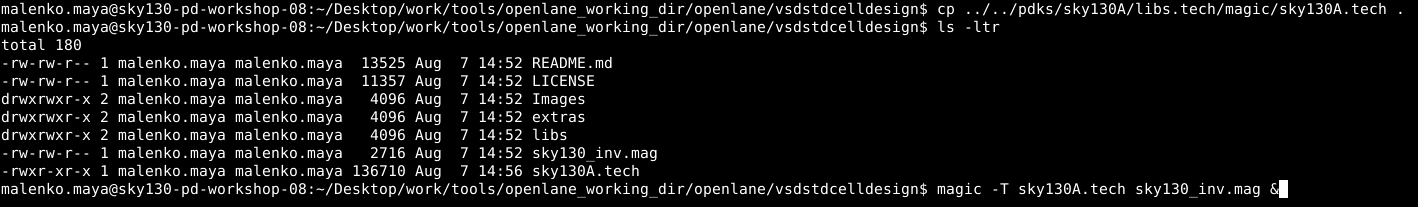
We first copy the
sky130A.techfile into the cloned repo. This file gives all the information about the SkyWater sky130 fabrication process:
-
We can see the layout of the invertor using magic:

-
To extract it to SPICE we use the following commands in
tkcon:

-
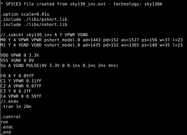
This is the content of the newly created
sky130_inv.spice:

-
After defining the extra connections (i.e.,
Vdd, Vss, Va) and changing some parameters, the file looks like this:
-
When we pass this file in
ngspice, we get the following output:

-
The plot of the inverter look like this:

-
Next, we will do a library characterization of the inverter. Characterization is the last step and gives the timing, noise, and power information. The timing characterization, in turn, includes timing treshold, propagation delay, and transition time.
-
The rise transition time (20% to 80%) is approx.
2.20-2.16 = 0.04 ns

-
Similarly, the fall transition time (80% to 20%) is approx.
2.12 - 2.17 = 0.05 ns

-
The cell propagation delay (cell rise delay) is approx.
2.18 - 2.15 = 0.03 ns


-
The cell propagation delay (cell fall delay) is approx.
4.05 - 4.04 = 0.01 ns


-
A LEF file is used by the routing tool in PnR design to get the location of standard cells pins and route them properly. It is the abstract layout form of a standard cell. Therefore, we will extract a
.leffile out of the magic inverter.magfile and then plug it into the picorv32a flow. -
First, we need to make sure that several pre-conditions about the standard cell layout are met. (1) If we open the invertor magic file, we have to make sure the I/O of the invertor (i.e., A and Y) are on the intersection between the horizontal and vertical tracks of layer
lit1. (2) The width of the standard cell should be in the odd multiples of the x-pitch (0.46 um). The same should hold true for the hight of the standard cell.

-
Then, after we configure the ports by defining their
port classandport useparameters, we generate the.leffile using the following command:


-
We copy the generated
.leffile to thesrcfolder of the picorv32a design:

-
We copy the libraries:

-
We modify the
config.tcl:

-
We prep the design:

Note:
prep -design picorv32a -tag <tag name of the run> - if we want the results from the last run, or
prep -design picorv32a -tag <tag name of the run> -overwritre - to overwrite the last configuration with the new values in the config.tcl file.
-
and include the additional
.lefinto the flow:

-
After
run_synthesiswe can see the new cells (i.e.,sky130_vsdinv):

-
but we can also notice a slack violation ❗

-
Current values:
Chip area for module '\picorv32a': 147950.646400
tns -3232.44
wns -26.53 -
In order to try to reduce the slack, we modified the following switches:

-
The new values after synthesis are (after removing/renaming the old
picorv32a.synthesis.vfile):
Chip area for module '\picorv32a': 209179.369600
tns -266.36
wns -2.95

-
Then we
run_floorplan. Since this command produced an error, it was suggested to use the following separate commands which give an error-free flow:
init_floorplan
place_io
global_placement_or
detailed_placement
tap_decap_or
detailed_placement
gen_pdn -
After
global_placement_or:

-
After the second
detailed_placement:

-
To check whether the custom inverter cell is added to the current flow, we invoke
magicand search for thesky130_vsdinvcell:

-
Next we will perform pre-layout static timing analysis (STA). STA ensures that all timing constraints are met, and that the circuit runs at the designated clock frequency.
-
In
<path_to>/openlanewe created thepre_sta.conffile, on which the pre-layout static timing analysis is based.

-
After running
sta pre_sta.conffrom theopenlaneflow, the following setup violations are reported:

-
I tried lowering the
SYNTH_MAX_FANOUTswitch from 6 to 4 (i.e.,set ::env(SYNTH_MAX_FANOUT) 4), but the slack increased:

-
Next, we will try to optimize the fanout values of some cells. The cell
_42923_had a very big fanout:

-
So I tried to replace it with the following cell:

-
The slack improved a bit, but it is still significantly high:

-
I tried to modify the other high fanout
mux_2_1cells, but the slack did not improve 😕 -
To verify that the netlist is modified we will search for the cell
_42923_and verify it was changed fromdfxtp_2todfxtp_4:

-
After we made these changed in OpenSTA, we should make sure that openLANE will use them:

-
Next we do floorplanning and placement using the commands mentioned before:
init_floorplan
place_io
global_placement_or
detailed_placement
tap_decap_or
detailed_placement
gen_pdn -
After
global_placement_or:

-
After the second
detailed_placement:

-
Finaly we run the clock tree synthesis
run_cts


-
The next step is to do the post-cts timing analysis.
-
We execute
openroadin the openLANE environment and we will do the timing analysis with openSTA from there. We read the.lefand.deffiles and create the.dbfile:

-
Next we execute the commands which were previosuly loaded from
pre_sta.conf:

-
The value of the hold slack is:

-
The value of the setup slack is:

-
However, this analysis does not give the real numbers for the slack values.
-
Therefore, we execute the following commands, where we load the other liberty file:

- And this is the output:
- The value of the hold slack is:

- The value of the setup slack is:

- And this is the output:
-
Both slacks are met, the clock tree synthesis doesn't have any violations.
-
Let's try to modify the
CTS_CLK_BUFFER_LISTand remove thesky130_fd_sc_hd__clkbuf_1buffer

-
We have to forcefully stop the
run_cts, since it was stuck! We have to update the.deffile andrun_ctsagain:


-
Next, we execute the same commands as before:

-
The value of hold slack is:

-
The value of setup slack is:

-
Both hold and setup slacks have improved, on the expense of the area. The setup slack improved from
4.1607to4.2278, while the hold slack improved from0.1049to0.3160. -
Next steps will be routing and post-routing STA.
-
In the video, the next step was to run
gen_pdnfor basic power grid generation. Since we included this step in the new set of commands before, we didn't run it this time. -
We can see the
pdn.defcreated before:

-
Finally we do the routing with
run_routing. The routing engine used is TritonRoute. Since we used the defaultROUTING_STRATEGY(i.e., TritonRoute = 0), the routing finished with 5 violation (in 64 optimization runs). In case we choseTritonRoute = 14, the number of violations would have been zero, on the expense of a very time consuming routing process and memory utilization.


-
The violations can be manually modified in
<path_to_run>/reports/routing/tritonRoute.drc
